Today I have finally tested out my micro controller project of which I am using to control the reaction and to keep the h-cat reaction at a set temperature, I am doing this by controlling the ambient air intake fan.
The minimum fan duty cycle is 40% any lower and the motor fails to spin, I wanted to have a minimum air flow to ensure the HHO gas is forced out and not allowed to accumulate, this reduces the risk of flash back.
With the pre-heater on and the fan at minimum duty the max exit barrel temp reaches around 170 Celsius and the second probe an inch prior to the pre-heater sitting at around 100 Celsius. As you can see in the picture above.
I was beginning to find the boundaries of my parameters and pushed up to 230 Celsius before the PWM failed and some overheating in the HHO electrolysis cell wires ended today's work.
I've had so many snags along the way, firstly with power supplies of which I have successfully solved using a rotor-verter setup, blocked torches causing pressure build up and subsequent leaks, getting enough power to the HHO cell for more gas and so on! It's certainly not for the light hearted experimenter.
A quick video showing my efforts so far is below!
15th of November 2014
Well folks I just want to say that I've finally had success with my first working iteration of a HHO & car catalytic converter to create a device for heating.
Due to it's intake of ambient air the nitrogen and oxygen will react to create NOx which is not good for your health so don't try this in an enclosed space, ensure you have plenty of ventilation and be careful working with explosive gases.
Simple Design of HHO CAT
In a nut shell this design is blowing in ambient air or an inert gas to dilute the HHO mixture and force it away from the inlet pipes over the catalyst generating extra heat which the heat sink prevents from traveling towards HHO gas, keeping it below ignition temperatures. The bit I'm missing is what I do with that heat. Which you can see in the rough drawing above will be to pump it through a heat exchanger.
I recorded a quick video to demonstrate that the heat generated is beyond what the resistor is creating.
The resistor was creating around 36 deg C, the HHO got it up above 70 deg C over an inch air gap.
I also shot another video wondering what would happen if I shutdown the resistor heating. Turns out it will continue to run, however my battery was drained and began to loose gas production meaning the reaction began to cool.
Wired up the controller temporarily, still getting issues with heat after putting in 10mm squared cable, seems to be in the brushes now.
Updates for 30th October 2014
Found a 48v 400a controller on ebay for £100, so going to use this for time being. It is made by Navitas and is commonly used in forklifts and golf carts.
Updates for 10th October 2014
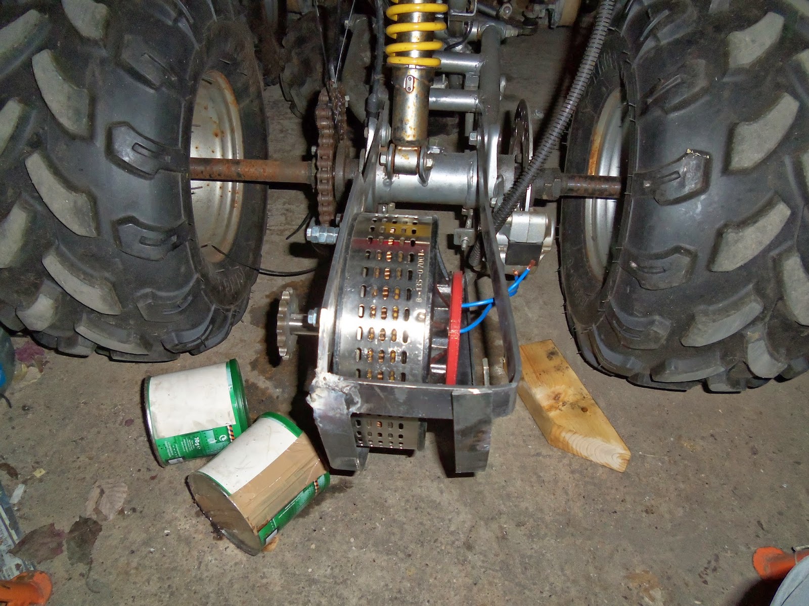
I had previously used a 3d printed part to hold the sprocket onto the motor which surprisingly held up at 12 volts. Well it lasted a millisecond when I tried 48 volts, hey ho I expected that.
One of todays tasks was to make the sprocket holder in metal. After wasting time with precision engineering firms etc I decided to start with a '1610 Powerdrive Taper bush' for less than a tenner with 6mm key steel.
I had to drill the bolt holes, so I used a couple of sockets and some card wrapped around to keep the bush and sprocket central, I then drilled through the sprockets bolt holes to mark where I needed to drill before removing the sprocket and finishing off the holes.
The next task was to fillet off one side to make clearance for the chain like in the models above. To do this I grabbed a long socket and put the bush on whilst holding this to a bench grinder allowing the bush to spin but not too fast, so some friction is required, so wear gloves or loose fingers!
The only other thing I had to do was counter sink the non chain side of the bolt holes as this bush is quite deep, I found out I had no space and the chain was out of alignment.
It is still very Heath Robinson at the moment, eg jumpleads are too thin so they get quite warm, my speed controller is a couple of bits of metal jammed into a pedal config hot glued onto the quad etc.
Todays run was at 24 volts, video is below enjoy!
I had an old faulty controller lying around so i'm going to give a new lease of life! It could never deliver enough current, so i'm going to use it as the driver for my bank of power mosfets. So far it is working on my bench, yay!
Updates for 5th October 2014
I wanted to test the drive train so I threw on a 12 volt battery and made a make shift foot pedal on off switch (it crackles a bit). You can see for yourself it goes just great (not fast with only 12v, 10+mph).
So now the next stage is to stretch out the frame to accommodate more batteries, rework brakes and steering positions and see where I end up.
Updates for 28th September 2014
Motor Mount finished and raised several inches
Chain shortened and tension adjusted
Project Started 9th of September 2014
Well I've took it upon myself to build an affordable electric vehicle, sure I'm not likely to have the luxuries of an automakers offerings, but I'm pretty sure I can do it for under a few grand!
Now due to some steep learning curves, I have not got the project to the point I was happy to post. However I have decided to just post some build pictures I have.
3D Scanning 'real world frame' into CAD
I will just point out that whilst I have successfully used a kinect sensor to scan a 3d image of the quad frame I'm remodeling, it has not been without frustration. So therefore I would recommend anyone attempting similar feats have high end CPU and a nvidia CUDA capable card to prevent despair of relocating to last position or software utterly loosing the plot at slow frame rates! I found 'ReconstructMe' to be better suited than 'Scannect'.
The other thing to note is the number of triangles in the acquired 3d scan, they will be in the order of 250k, you need this to be at 10k for certain cad programs to import natively else they will run at a turtles pace. Hopefully soon I will have concept drawings online!
I used Meshlab to trim out and cleanup the scan data, your best to do this with the high poly count(it will chug a bit), make sure to use the wire frame to spot hidden clumps (these waste your detail when you come to reduce the poly count later), I was switching between this and the standard view. when trimming I was mainly using the select faces, using 'esc' to switch into view orbit mode, 'ctrl' to add more selections, and 'alt' to select only viewable faces, and 'shift' to remove accidental selections. Once thats done I run 'Filters' > 'smoothing, fairing and deformations' > 'Laplacian Smooth' using defaults.
Then I run 'Filters' > 'remeshing, simplification and reconstruction' > 'quadric edge collapse decimation' set options as below, we are aiming for 10k polygons so it can import into other cad tools.
3D Scan data after cleanup and and splitting. Each section is only 10k polys so looks rougher.
// p2v pre migration driver injection Lsilogic controller for vmware
Import Reg files on the source migration server .sys files need to be copied to %windir%\systems32\drivers system should boot and no post migration task need be performed
// p2v post migration driver injection lsilogic controller for vmware failure to do pre migration task will result in stop 7b error/blue screen to resolve; 1. boot hirens bootcd on the vm and select 'mini windows xp' 2. when booted, click the Hiren menu icon in the tray -> Registry -> Registry Editor PE. 5. When asked to, set the remote Windows directory (usually C:\Windows) and press OK. 6. Click OK on each window to select the related registry hive. If you want to edit a registry
value from HKEY_CURRENT_USER you will need to select Yes when asked if you want to load an
NTUSER.DAT and locate the file in the user directory, however this is not required. 7. Expand HKEY_LOCAL_MACHINE and the hives will automatically load with the _REMOTE_ prefix.
Navigate to _REMOTE_SYSTEM. Check the number of the ControlSet, reg files have been made for 001
and 003, if another number shows up then you'll have to copy a set and edit accordingly. 8. Goto File > import all reg remote control set00X that are required one by one. 9. .sys files need to be copied to %windir%\systems32\drivers on the offline os reboot and system should boot.
I think electric bikes are great, theres nothing greater than whizzing somewhere on one until the batteries go flat. So I figured I could use off the shelf parts and knock up my own prototype vehicle.
After some trial and error, more error than trial, i've come to point where I am satisfied with my efforts and want to share it with the world since I've not seen many other people fuse this simple idea into reality.
I took my standard bicycle (£100) and added an electic motor kit (£250), plus sealed lead acid battery 12ah @ 48v (£90), it is great as is and can acheive 10miles with combined cycling, now that's not enough to get me work yet alone home. And I assure you upto the 12th mile this was very arduous with 20kg extra weight and flat batteries.
So I picked up a cheap bicycle trailer (£30) and a cheap petrol generator 800w from aldi for £70. The problem here is howto to tranform the mains voltage to something that the bike controller is happy with, and theres over current protection to think about also. I initially thought about using a stepdown transformer but they are expesive and hard to get at the spec i needed. I tried an arc welder, but the voltage was a little low and the current too high. I could rewind it a little but I want to get results fairly quickly, so I instead opted to use regular computer PSU used in parrallel to get the voltage needed, plus they were rescued from the skip.
The biggest problem is the motors inrush current ~35amp, the psu's I had were max 18amp, so they would go into protection mode and shutdown. I originally wanted to use the power from the generator alone, but because the psu's kept tripping I added in the battery as a buffer. I could use a resistor but the commercial products would cost hundreds (needed 3.3ohm 1080w), so I used some springs as resistors, they will probably get hot and possibly melt, I'm hoping they last long enough for me to assess the range gain I can get.
So thats where i'm at with this idea, it's not pretty or efficient this I know. My first run was 8 miles with a battery at 50v which dropped to 47v, at that point I had no bridge rectifier or resistor, and I suspect the battery was being drained first, as i was only using 4 psu's 48v.
I suspect now that the source with greatest voltage will be drawn upon first, and without the resistor on my now 5 psu's 60v it would shutdown a couple, but now it draws from the psu upto 15-18 amp ensuring they all remain on and then draws upon the battery for another 7-9 amp.
I'm thinking of adding some big cap's after the resistor to provide some burstable current as really I want to be able to operate in 3 modes, Engine Only, Battery Only and Both.
Hopefully the storm will be over and tomorrow I can get some stats.
Where i'm ultimately going is for a custom tricycle like a velomobile, and an electric start generator with a custom winding so I can do away with the 4-8kg of PSU's, maybe mod the engine with HHO or a fuel vapouriser, and possibly think about a huge joule thief for auxiary lighting, and perhaps smoothing caps, and I could think about regen braking into a super cap bank.
Having started my fascination with 3d printers back in 2011 when an associate showed me some youtube vid's, I was completely mesmerized by how cool they were. Then I would dream of all the things I could make, then the things I could design, and blah blah blah then metal printing and so on.
So that was it the Idea had been seeded and I decided to plunge into something I had absolutely no idea about or even where to begin. Having done a bit of search engine revision wolf strapping had caught my attention, so that was it I spent one weekend with a pile of wood some draw runners and knocked up 2.5ft by 2.5ft by 2.5ft monster of a frame. And the following week my large stepper motors had arrived Nema 24 I think, fist sized anyways. Then I got some pulley/cogs but they needed boring out, needless to say I did this unfortunately not in a straight manner! I was so excited I just wanted to click my fingers and it would be built! Anyhow I'd got this contraption to a reasonable state and with the Makerbot electronics I'd ordered I had one heck of a time getting the machine calibrated just for correct axis movement. It was quite exciting seeing something I had built in motion, Computers tend to be rather static!
It wasn't until it was built to this point that I realized why the wolf strap never really had any descent documentation, It was a bad design especially exasparated by my over sizing, The Z axis would flap 10-20mm. So ok I made a mistake and it was time to move on, So this time I ordered a reprap mendel frame, of which my nema 24's wouldn't fit so I ordered the right motors and hey ho onto the next stage.
Hotend design, still in my rep strapping idea I made a hotend from fire crete and some brass tube I threaded and a heatsink drilled and tapped, I kind of got it to work a little but staying at temp was an issue, eventually I got fed up and ordered a parcan hotend, much smaller than the one I made lol.
So my next problem was getting a decent print on a makerbot driven mendel using replicatorG! I think this was my biggest mistake, but anyhow I took to IRC and asked lots of questions but no one would help someone with makerbot tronics, fortunately scribbleJ was great, so i'd loaded sjfw onto it ditched repg and used pronterface! I was in business finally, prints were coming out quite good, even got a few upgrades printed, then one day it wouldn't print. Boy was I pissed, I mean I had many moments when I thought about just tossing the printer on the floor, but that day was the worst. printer finally worked for what seemed like 5 mins then the extruder fried...... something I should chase reprap.me up for actually!
Well what you'll find is 3d printing can be like this alot, one minute fine the next a problem! so given the lack of support for MB stuff I was looking for the next best tronics I could get, now not being to adept at this hobby I applied computer buying logic...... go for the biggest number init! so I ordered a Gen7 kit off ebay, built the thing then spent months trying to get it to work. I would have a couple of problems in teacup then in sprinter the problems would switch somewhere else. but in anycase between the two all hardware was tested as fully functional so no my soldering was not the issue, any way I binned the gen7 and ordered a sanguinololu 1.3b and the ramps 1.4 i think, which could be used with the arduino mega I had! I did this to be sure I could get my printer working again. fortunately I chose the sanguino to try first and touch wood it's been brilliant since!
Oh I forgot to mention Use the best oil you can buy and oil daily for best results. seriously I had major issue on my z axis until I used a decent oil


.JPG)
.JPG)


.JPG)
.JPG)
.JPG)
.JPG)
.JPG)
.JPG)
.JPG)
.JPG)
.JPG)